FAQ
Frequently Asked Questions
DC-Side
The ratio of PV module STC power rating to inverter output power rating N often referred to as “Stacking Ratio.” Most PV installations are designed for a stacking ratio greater than 1, and less than 1.5. However, the only real limitation on stacking ratio for the HiQ inverter is the voltage and current limitations of the string inputs. The Vmp range for the string inputs is 425 to 850VDC. The specified maximum short circuit current of the DC source is 30A. Two strings with a Vmp of 850VDC and a short circuit current capability of 30A would yield a stacking ratio of almost 6.375 (8 kW) and 8.9 (5.75 kW), which are obviously excessive.
A more practical limitation is due to the power and current limits imposed by the inverter firmware. Input power is limited to 5kW and input current is limited to 10A per string by the firmware. The total of these two strings exceeds the output power limit of 8kW, to in reality something less than 5kW would be harvested from each string.
The maximum input current on each string is 10A for maximum output power. However, the ‘DC maximum input short circuit current’ for each input, i.e. the maximum current the unit is rated for under fault conditions, is 30A. Therefore there is no issue with use of modules with Isc’s up to this value.
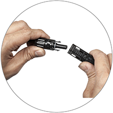
The TrueString product is a non-isolated inverter for use with ungrounded DC systems
and the 208V TrueString inverter, the connectors are the certified means of
disconnect. More background on this topic may be found in theapplication note shown here.
These are manufactured by Renhe Solar (www.renhesolar.com).
For more details, please contact them directly: ian@renhesolar.com
AC-Side
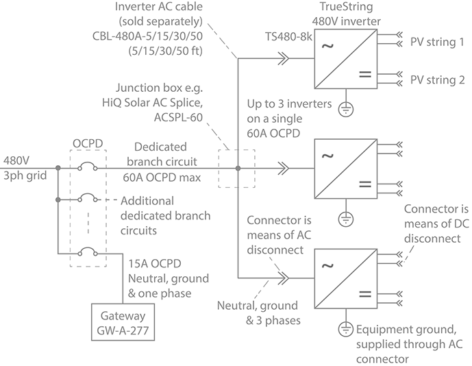
The metal enclosure of the inverter must be grounded per NEC 690.43. Equipment ground is provided through the AC connection. Optionally, grounding may be achieved also through attaching an Equipment Ground Conductor (EGC) to a lay-in lug (not provided) attached to the chassis.
Grounding may also be achieved using the mounting bolts to any properly grounded metallic structure provided a paint-cutting washer is employed, such as a stainless steel star washer.
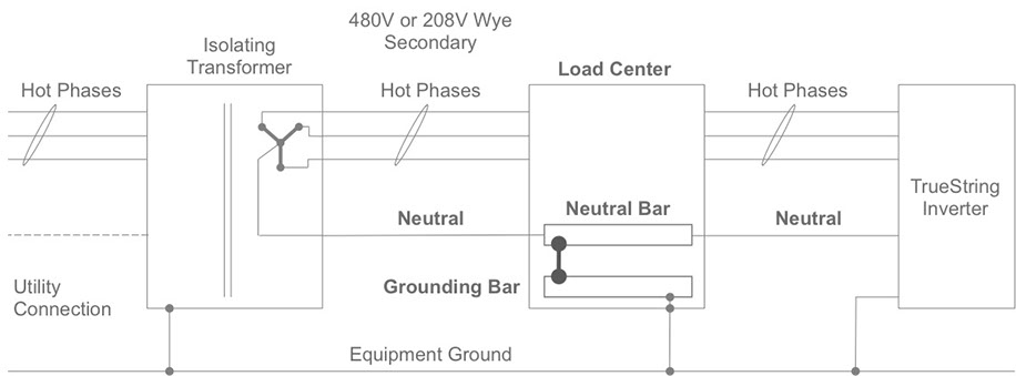
All 5 circuits (L1, L2, L3, Neutral, Ground) must be connected and Neutral must be bonded to earth ground. Failure to do so can damage the unit and void the warranty.
The HiQ inverter exports power only on the Line conductors. The neutral conductor is used solely for voltage sensing and PowerLine communications.
and the 208V TrueString inverter, the connectors are the certified means of
disconnect. More background on this topic may be found in theapplication note shown here.
Our inverters easily comply with this requirement. More details may be found here.
This is answered comprehensively in the document here.
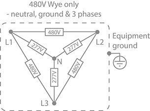
- The inverter must have wye grid connection (3 hot phases, neutral & equipment ground)
- Neutral MUST be bonded to equipment ground or damage to the inverter may result
- Transformers are often isolating – so the neutral may lose any path to equipment ground that was provided elsewhere, once the transformer is inserted into the circuit
- Example is shown below where neutral is bonded to equipment ground in the load center, but many other system configurations and methods are possible
- Utility side of transformer – configuration to be determined by the design engineer to suit site requirements